22.1. Overview of the User Symbols Module 22.1.1. Elements 22.1.2. Attribute Classes 22.1.3. Model Classes 22.2. Uses of the Usersymbols Module 22.2.1. Defining Reusable Symbols 22.2.2. Elements Without Semantic Implications 22.2.3. Defining a Specific Graphical Rendition for a Semantic Element 22.3. Positioning and Coordinates 22.3.1. Axis Orientation 22.3.2. Units 22.3.3. Positioning 22.3.4. Curve Shape 22.4. Line Rendition 22.5. Limitations
22. User-defined Symbols
This chapter describes the elements, model classes, and attribute classes that are part of the MEI.usersymbols module.
22.1. Overview of the User Symbols Module
The module described in this chapter makes available the following components:
22.1.1. Elements
22.1.2. Attribute Classes
No attribute classes are defined in this module.
22.1.3. Model Classes
The usersymbols module defines the following model classes:
22.2. Uses of the Usersymbols Module
The elements provided by the usersymbols module may be used in two ways:
- For defining lines, curves and text elements that cannot be represented by a more specific element.
- For defining reusable symbols and special graphical renditions.For this purpose, it provides three elements as graphic primitives, line, curve and anchoredText. Anywhere these elements are allowed, the symbol element can be used as well. The symbol element facilitates the re-use of symbols that were defined by symbolDef elements.
22.2.1. Defining Reusable Symbols
The symbolDef element uses SVG markup or the aforementioned graphic primitives to describe a symbol. A symbol definition may also use symbols defined by other symbolDef elements by employing the symbol element.
          <symbolDef xml:id="userSymbols.triangleSymbol3">

             <line x="0" x2="2.55" y="0" y2="4.25"/>

             <line x="2.55" x2="5.1" y="4.25" y2="0"/>

             <line x="5.1" x2="0.85" y="0" y2="0"/>
             </symbolDef>

        <symbolDef xml:id="userSymbols.triangleSymbolWithStick">

           <symbol ref="#userSymbols.triangleSymbol3"/>

           <line x="2.55" x2="5.95" y="1.25" y2="3.4"/>
           </symbolDef>

22.2.2. Elements Without Semantic Implications
The graphics primitives and symbols can be used directly in the music to describe text and lines on a purely graphical level, without implying a specific logical meaning. If possible, however, more meaningful elements should be used. This means for example, “a tempo” or “da capo” should in general not be put inside anchoredText. Instead, tempo and dir should be used. Likewise, slurs and ties should be encoded using their respective elements, not using curve, and for glissandi, gliss should be used instead of line.
An example usage for line is the visualization of voice leading, which is not covered by a specific MEI element.
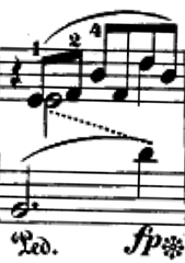
        <measure n="6">

           <staff n="1">

              <layer n="1">

                 <rest dur="4" xml:id="userSymbols.r1"/>

                 <beam>

                    <note dur="8" oct="4" pname="c" xml:id="userSymbols.n1"/>

                    <note dur="8" oct="4" pname="e" xml:id="userSymbols.n2"/>
                    </beam>

                 <beam>

                    <note dur="8" oct="4" pname="g" xml:id="userSymbols.n3"/>

                    <note dur="8" oct="4" pname="e" xml:id="userSymbols.n4"/>

                    <note dur="8" oct="4" pname="b" xml:id="userSymbols.n5"/>

                    <note dur="8" oct="4" pname="g" xml:id="userSymbols.n6"/>
                    </beam>

                 <slur curvedir="above" endid="#userSymbols.n6" startid="#userSymbols.n1"/>
                 </layer>

              <layer n="2">

                 <rest dur="4"/>

                 <note dur="2" next="#userSymbols.n9" oct="4" pname="c" stem.dir="down" xml:id="userSymbols.n7"/>
                 </layer>
              </staff>

           <staff n="2">

              <layer n="1">

                 <note dots="1" dur="2" oct="2" pname="g" xml:id="userSymbols.n8"/>

                 <note dur="4" oct="3" pname="b" prev="#userSymbols.n7 #userSymbols.n8" xml:id="userSymbols.n9"/>

                 <slur curvedir="above" endid="#userSymbols.n9" startid="#userSymbols.n8"/>
                 </layer>
              </staff>

           <line endid="#userSymbols.n9" rend="dotted" startid="#userSymbols.n7"/>
           </measure>
22.2.3. Defining a Specific Graphical Rendition for a Semantic Element
Usersymbols can define the rendition of different elements in two ways. Some elements, for example dir and tempo, can have user symbol elements as content. In the following example, the content of dir is used to provide pictograms of percussion instruments.

        <section>

           <scoreDef meter.count="4" meter.unit="4">

              <symbolTable>

                 <symbolDef xml:id="userSymbols.triangleSymbol1">

                    <line x="0" x2="2.55" y="0" y2="4.25"/>

                    <line x="2.55" x2="5.1" y="4.25" y2="0"/>

                    <line x="5.1" x2="0.85" y="0" y2="0"/>

                    <line x="2.55" x2="5.95" y="1.25" y2="3.4"/>
                    </symbolDef>

                 <symbolDef xml:id="userSymbols.cowbellSymbol">

                    <line x="1" x2="1.8" y="0" y2="4"/>

                    <line x="1.8" x2="4.2" y="4" y2="4"/>

                    <line x="4.2" x2="5" y="4" y2="0"/>

                    <line x="5" x2="1" y="0" y2="0"/>

                    <curve bezier="0 1.5 0 1.5" endho="3" endvo="4" startho="1" startvo="4"/>
                    </symbolDef>
                 </symbolTable>

              <staffGrp>

                 <staffDef clef.line="2" clef.shape="G" n="1"/>
                 </staffGrp>
              </scoreDef>

           <measure n="1">

              <staffDef n="1">

                 <instrDef midi.instrname="Open_Triangle"/>
                 </staffDef>

              <staff n="1">

                 <layer>

                    <dir tstamp="1">

                       <symbol ref="#userSymbols.triangleSymbol2"/>
                       </dir>

                    <note dur="1"/>
                    </layer>
                 </staff>
              </measure>

           <measure n="2">

              <staffDef n="1">

                 <instrDef midi.instrname="Cowbell"/>
                 </staffDef>

              <staff n="1">

                 <layer>

                    <dir tstamp="1">

                       <symbol ref="#userSymbols.cowbellSymbol"/>
                       </dir>

                    <note dur="4"/>

                    <note dur="4"/>

                    <note dur="4"/>

                    <note dur="4"/>
                    </layer>
                 </staff>
              </measure>
           </section>
A number of elements can point to an internally-defined symbol for rendering using the @altsym attribute.
        <scoreDef>

           <symbolTable>

              <symbolDef xml:id="userSymbols.clefA">

                 <curve bezier="-1.2 0.1 -0.9 -0.8" endho="1.1" endvo="6.6" startho="1.2" startvo="4"/>

                 <curve bezier="1 0.9 0.1 1.6" endho="3" endvo="5.3" startho="1.1" startvo="6.6"/>

                 <curve bezier="-0.1 -2.6 0 2.3" endho="0.6" endvo="-0.1" startho="3" startvo=" 5.3"/>

                 <curve bezier="0.07 -1.3 -0.2 -1.63" endho="2.4" endvo="0.23" startho="0.6" startvo="-0.1"/>

                 <curve bezier="0.2 1.3 0.5 0.62" endho="0.8" endvo="0.81" startho="2.4" startvo="0.23"/>
                 </symbolDef>

              <symbolDef xml:id="userSymbols.clefB">

                 <curve bezier="-0.7 0.1 0.3 0.92" endho="0.7" endvo="-0.2" startho="2.5" startvo=" 1.3 "/>

                 <curve bezier="-0.27 -0.76 -1.25 -1.26" endho="2" endvo="-0.74" startho="0.7" startvo="-0.2"/>

                 <curve bezier="1.4 1.8 0.4 -1" endho="1.6" endvo="4.36" startho="2" startvo="-0.74"/>

                 <curve bezier="-0.89 2.2 -1.1 1.6" endho="3.5" endvo="6.06" startho="1.6" startvo="4.36"/>

                 <curve bezier="0.8 -1.2 0 0" endho="3.7" endvo="2.66" startho="3.5" startvo="6.06"/>
                 </symbolDef>
              </symbolTable>

           <staffGrp>

              <staffDef n="1">

                 <clef altsym="#userSymbols.clefA" line="2" shape="G"/>
                 </staffDef>

              <staffDef n="2">

                 <clef altsym="#userSymbols.clefB" line="2" shape="G"/>
                 </staffDef>
              </staffGrp>
           </scoreDef>
Externally-defined symbols may be referenced using a @glyphname or @glyphnum attribute. Both attributes refer to Standard Music Font Layout (SMuFL) characters. Other character sets must be treated as internally-defined character sets.
<meterSig count="2" form="norm" glyphname="timeSigCutCommon" glyphnum="U+E08B" sym="cut" unit="4"/>
22.3. Positioning and Coordinates
22.3.1. Axis Orientation
MEI uses the classic axis directions where the x-axis points from left to right and the y-axis points from bottom up. (This is compatible with PostScript’s axis orientation, while SVG’s y-axis points in the opposite direction.)
22.3.2. Units
There are two types of units used by MEI: Staff units (data.MEASUREMENT) and units of the output coordinate system. Units of the output coordinate system can be translated to physical real world distances by means of the @vu.height and @page.scale of a scoreDef element. Real world units are multiplied by the value of @page.scale to get the corresponding value in output coordinate units.
If an element is scaled using the @scale attribute, the actual size of the units changes accordingly.
22.3.3. Positioning
An element may be positioned using either absolute or relative coordinates. If absolute start point coordinates are specified using @x/@y coordinates (or their relatives @x2/@y2 for endpoints) they take precedence over relative positions specified by @ho/@vo/@to (or @startho/@startvo/@startto). Analogously, @x2/@y2 override @endho@endvo/@endto.
If @to/@startto/@endto attributes are used, the start or end point is x-aligned with the indicated timestamp.
If relative start coordinates (@ho/@vo or @startho/@startvo) are used, the origin of the coordinate system to be used for the start point is the first one found by the following search schema:
- If @startid is present, the origin of the referenced element;
- If the element is inside running text (e.g. inside tempo), the end of the preceding text or element;
- Otherwise, the origin of the containing element.
The start point is offset from this origin by the value of the start coordinates (@ho/@vo or @startho/@startvo), using staff units.
Analogously, the endpoint is determined using end coordinates (@endho/@endvo). If @endid is specified, it takes precedence over @startid.
Examples of origins are:
- staff and layer: The horizontal origin is the starting point of the measure, the vertical one is the bottom staff line;
- note: The horizontal origin is the left end of the notehead, the vertical one the center of the notehead;
- clef: The horizontal origin is the left end of the clef, the vertical one the line specified by clef/@line (or @clef.line);
- For elements containing text: The left end of the baseline;
- symbolDef: As symbol definitions aren’t rendered directly, their coordinate system and origin are considered virtual. When they are referenced by symbol or @altsym, the origin of the context, i.e. the referencing symbol, is used.
If neither absolute nor relative coordinates are specified, determining visually suitable start and end points for @line and @curve attributes is left to the rendering application. A value of 0 is not always assumed for absent relative coordinates. A typical example where a rendering application may not choose the origins of absent relative start and end coordinates to be the start point as well is the line connecting two notes in the above Schumann example.
22.3.4. Curve Shape
If neither a @bezier nor @bulge attribute is present, the renderer determines a suitable shape. However, if @curvedir is present, the curve must respect the curvature direction specified there.
The attributes @bezier and @bulge define the shape of a curve in two different ways. If both are present, a rendering application may choose either one. They override @curvedir.
@bezier defines the inner control points of a cubic Bézier curve, i.e., a Bézier curve with two inner control points. The coordinates are given by a space separated list, first x and y offsets for the first control point, then x and y offsets for the second one. The x and y offsets are given in staff units (or inside the context of symbolDef in abstract units). The offsets for the first inner control point are relative to the start point, the ones for the second inner control point are relative to the end point.
The @bulge attribute allows specification of the curve shape by a number of interpolation points. The interpolation points are given by their distance from the line connecting the start and end point. The distance values are stored as a space separated list.
The interpolation points are calculated as follows: If @bulge provides n distance values, the connection line is divided into n+1 subsegments of equal length. The interpolation points are found by drawing a perpendicular line of the respective length at each subsegment joint. Positive distance values are drawn to the left of the connection line (left when traveling from start to end), negative ones to the right.
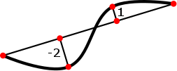
The interpolation algorithm used by the rendering application is implementation dependent.
22.4. Line Rendition
The @form attribute of lines may take the following values:
- dashed
- dotted
- solid
- wavy
These attribute values are only qualitative. Actual dash length and dot and dash spacing are implementation dependent.
The @width attribute may take the following values:
- narrow
- medium
- wide
These values are also qualitative, however, they are also relative. That is, ‘narrow’ is the default value, ‘medium’ is twice as wide as ‘narrow’, and ‘wide’ is twice as wide as ‘medium’.
In addition to these textual values, the width attribute may contain a numeric value and an optional unit value, “2mm” for example. If the unit value is not provided, staff interline units are presumed.
The @lstartsym and @lendsym attributes name the symbol that may start and/or end a line, while @lstartsymsize and @lendsymsize indicate the relative size of the symbol using a numeric value in the range from 1 to 9.
22.5. Limitations
The usersymbols module does not currently support continuous composite lines or filled areas. As mentioned above, the rendition of lines is highly implementation dependent. Coordinate system transforms are restricted to scaling using @scale.